Sizing a
Biofilter
Sizing a biofilter can be a daunting task for the novice in the aquaculture industry. One has to pick and choose between many technologies and options. Once you have chosen a type of biofilter there are still a tremendous number of variables to consider and make decisions about. Due to the wide disparity in the data reported in the literature, it is wise to oversize biofilters or provide for a modular design that will allow for expansion. Trickling filters are relatively easy to design and build. Here is an example of a simplified procedure for a trickling filter that may help to start the design process.
1. Estimate the maximum amount of feed you
will be feeding your fish at any time in the crop cycle. This will determine the maximum load the
biofilter will need to handle.
2. Decide or determine the TAN (total ammonia nitrogen) level that your fish will be able to tolerate with no ill effects. Based on the allowable ammonia concentration in the culture tank, determine the ammonia removal rate. Make a guess about the hydraulic loading rate that you will use. See Graph 1.
3. Decide on the amount of water that will flow through the biofilter.. One way to look at water flow is to calculate how long it will take for all of the water in the culture tank will pass through the filtration system. A very slow system might recirculate all of the water in 12 hours. A very fast system might recirculate all the water in 5 min. A good starting point for a lightly loaded system might be a 1 hr. turnover time. In other words, all the water in the tank is passed through the filter in 1 hour. For example, a 5000 gallon tank would need a flow rate of 5000 gallons per hour or 83 GPM.
If you are adding oxygen with a system that is external to your culture tank, your recirculating flow rate will probably be determined by the oxygen requirements of the fish. If your oxygen addition is within your culture tank, then the solids removal and biofiltration will guide your flow rate.
4. Based on the amount of feed to be used and the ammonia removal rate, calculate the total amount of surface area required for the biofilter packing.
5. Decide on the density or SSA (specific surface area) of the biofilter material. The three commonly used SSA's for structured media are 119, 69 and 48 ft2/ft3 (390, 226 and 157 m2/m3).
6. Divide the total amount of surface area required by the SSA of the filter material. This gives you the volume of biofilter media required.
7. Decide on the shape of the biofilter.
8. Determine the hydraulic loading rate. If the hydraulic loading rate is too low, either increase the water flow or make the trickling filter taller and narrower. The hydraulic loading rate influences the ammonia removal rate as shown in graph 1. In addition, there is a recommended minimum water loading rate based on the specific surface area of the media. The more surface area in a given volume, the more water is required to fully wet all the surfaces.
Specific Surface area Minimum Water loading
Sq.ft./cu.ft. GPM/sq.ft.
30 3
50 4
70 5
120 7
The sq.ft. in the water loading refers to the plan area (top area) of the trickling filter. The sq.ft. in the specific surface area refers to the surface contained in the packing or media.
Graph 1
This graph is based on the data presented in the very useful paper by Kamstra, Van der Heul and Nijhof “Performance and optimization of trickling filters on eel farms” Aquacultural Engineering 1998 p. 175 – 192. This graph gives approximate removal rates for warm, freshwater trickling filters with good water distribution and sufficient dissolved oxygen. Saltwater systems will have lower removal rates and cold water systems will have lower removal rates. New systems will have lower removal rates. Systems that have wide swings in ammonia concentration will have lower removal rates. Nitrifying bacteria are inhibited by light so filters exposed to bright lights will have lower results. Systems using various therapeutic agents like formaldehyde can have lower results. Use this graph with caution !! You may get better results but you can also get worse results. It is much better to include a generous safety factor than have a system limited by the biofilter. Lower ammonia concentrations are always better than higher concentrations. To the best of my knowledge, no fish ever died as a result of an oversized biofilter but many have died from undersized ones.
Here is an example of a sizing calculation:
Crop Size 500 kg (1,100 lbs.) of fish
Feeding rate 2% bw /day
Amount of Feed 10 kg (22 lbs.) at 32% protein
Allowable TAN 1.5 ppm
Water Flow 83 gpm
Amount of Ammonia Produced .03 x 10 kg = 300 gm/day
Ammonia Removal Rate .6 gm/m2-day at 6 gpm/ft2 hydraulic loading rate
Surface area required (300 gm /day)/( .6 gm/m2-day) = 500 m2
Convert square meters to ft2 500 m2 x 10.76 ft2/m2 = 5380 ft2
Packing density or SSA 69 ft2/ft3 (226m2/m3)
Volume of media =
(500 m2)/(226 m2/m3) = 2.21 m3
or
Volume of media = (4035 ft2)/(69 ft2/ft3) = 78 ft3
If we start with a stack of media 4 ft wide by 4 ft long by 5 ft high we get 80 ft3. Using the 83 gpm flow rate, the hydraulic loading would be about 5.2 gpm/ft2
Hydraulic loading 83 gpm/(4' x 4') = 5.2 gpm/ft2
This is higher than the minimum hydraulic loading rate for this media but lower than the 6 GPM/ft2 we guessed at when reading graph 1. The easy thing to do is to increase the water flow rate slightly to 96 gpm (4' x 4' x 6 gpm/ft2).
The above procedure is a simplified, general guideline for the process of designing a trickling filter. Predicting the amount of packing required for a given application is not an exact science. If the filter is undersized for the application, the level of TAN at design conditions may be higher than desired. Generally, it is wiser to oversize a biofilter rather than undersize it. Fish will not die from an oversized biofilter.
Other Design Concerns
One of the most important considerations in any biofilter design is providing all of the bugs (micro organisms) with a constant supply of food (nutrients) and oxygen. The reason the word "all" is emphasized because many biofilter designs do not distribute the flow of food and oxygen evenly. Some parts of the biofilter may have a high flow of water past them and other parts may have almost no flow. This is a common cause of poor performance by a biofilter.
Even hydraulic loading (water flow) throughout the filter is extremely critical to proper utilization of the biofilter media. Rotating Biological Contactors (RBCs) are consistently shown to have very high treatment efficiencies. This is because the media is consistently and evenly moved through the water to be treated. All of the bugs on the surface area contained in the RBC are exposed to a steady stream of food and oxygen. Trickling filters and submerged filters can achieve high treatment efficiencies if they also have a constant, even flow of water to all of the surface area contained in the filter.
Trickling Filters
We will begin the discussion of design with trickling filters because they are easier to design and size than a submerged filter. Once the size and shape of the trickling filter has been decided, the water distribution system must be designed. It cannot be overemphasized that the water must be evenly distributed over the top of the media. Areas that are dry will not provide any biofiltration benefit. In addition, the interface area between the wet and dry areas will tend to accumulate solids and eventually lead to plugging. In general, it is easier to evenly distribute the water for systems with high hydraulic loadings compared to low hydraulic loadings. There is no maximum water loading for structured packing.
There are two common ways to get an even distribution
using a fixed spray system. For square
or rectangular vessels one way is to use solid cone, square pattern spray
nozzles. The edge of each spray pattern
should touch the edge of each adjacent pattern.
This system is easy to visualize and design. The only requirement is that the nozzle spray
pattern must be well defined by the manufacturer so that the designer can size
the system properly. The most common
drawback to this system is that not all nozzles have an even spray pattern even
though they are sold as solid cone nozzles.
Very often the center of the spray pattern has a lower water loading
than the edge of the pattern.
The second way to get an even water distribution is to use many over lapping spray patterns. Often, the individual nozzle spray pattern is hollow but the combination of many patterns covering the same spot gives an even coverage. The main problem with this system is that the wall of the vessel will intercept a certain amount of water. Any water that hits the wall will generally not go through the filter media. In a very large vessel, this is not a problem because the ratio of the perimeter to the area is small. In small vessels this system will not work well.
There is a third method of distributing water that can be used in round vessels. Rotating arm distribution systems can give an even distribution if they are sized properly. They also have a low head compared to some spray systems. The drawback to rotating arm systems is the wear and tear on moving parts and the required maintenance.
Part of the art of designing a trickling filter is to balance the competing requirements on the design.
1. In order to keep the energy costs to a
minimum, the pumping head for the filter should be as low as possible. The maximum plan area covered by the filter
is determined by the minimum water loading.
2. In order to minimize the floor space used by the filter, the filter should be as tall as possible. The practical limitations are the height of the building, the head limits on the pump and the structural and stability considerations of the vessel.
3. A taller filter will have a longer flow path for the water. This means a more complete treatment of the water with each pass.
4. Taller filters will have higher specific water loadings. This means better flushing action, more turbulent water films and higher ammonium removal rates.
Trickling filters for industrial applications are sometimes 30 ft. tall. This is not practical for aquaculture systems. In general, trickling filters for aquaculture are between 3 and 10 ft. tall.
Submerged Filters
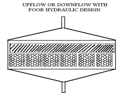
Submerged filters are excellent choices for small systems because they are very versatile. They can be located in a separate tank or in the culture tank. They can be horizontal flow, up flow or down flow. They can be aerated or not. The most important consideration for the design is the even distribution of water to the packing. It is very common for submerged filters to be designed as large, flat and thin sections of packing with water direction being up flow or down flow. There is typically no provision for distributing the water to all areas of the media. The length of the water path through the media is very short and the resistance to flow is very low. This is a recipe for disaster. The water flow will short circuit though a small section of the media and the rest of the biofilter will become anaerobic.
Ideally the flow path through a submerged filter should be as long as possible. A long thin raceway is the best. This type of biofilter is known as a long path, plug flow submerged filter. (see the paper written on this filter type). Another possible alternative is the use of aeration to induce a circulating flow around a tank. The key to properly designed submerged biofilters is the velocity through the media. The goal should always be to provide a high enough velocity through the media so that the flow is turbulent and all of the media has an equal flow of water. Equal flows of water insure a fresh supply of oxygen and nutrients to all of the bugs on the surface of the media.
Summary
While there are guidelines for the design of biofilters, it is not an exact science. Lightly loaded systems such as water gardens and koi ponds are more forgiving and sizing considerations are not very exact or critical. For intensive aquaculture systems, the biofilter represents a critical component of the system that may limit production if it is not designed or operated properly. Experienced professionals should be consulted by those persons intending to build systems where financial investments are at risk.
NOTE: This paper and other useful information for those interested in aquaculture, aquariums or related topics can be found on the web at http://www.biofilters.com
References
Greiner, A. D., Timmons, N. B., 1998. Evaluation of the nitrification rates of microbead and trickling filters in an intensive recirculating tilapia production facility. Aquacultural Engineering pp 189 - 200
Kamstra, A., Van der Heul, J.W., Nijhof, M., 1998. Performance and optimization of trickling filters on eel farms. Aquacultural Engineering pp 175-192
Saucier, B., Chen, S., Zhu, S., “Nitrification Potential and Oxygen Limitation in Biofilters” presented at the Third International Conference on Recirculating Aquaculture July 2000.
Timmons, M.B., Losordo, T. M., 1994. Aquaculture Water reuse Systems: Engineering Design and Management Elsevier Science B.V.
©1995-2013 by L. S. Enterprises. All rights reserved. No part of this publication may be reproduced or transmitted in any form or by any means electronic or mechanical, including photocopy, recording, or any information storage and retrieval system, without permission in writing from the publisher.
Published by L. S. Enterprises
PO Box 13925
Gainesville,
FL 32604 USA
Author: Matt Smith
Office 1-352-379-5626
Mobile
1-239-851-1175
Fax 1-866-706-1775
Email: mattsmith@biofilters.com
rev. 8/15/2013