Guidelines for CO2 Strippers
Abstract
The use of CO2 strippers is becoming more common as
RAS (recirculating aquaculture systems) become more intensive. Much has been written about the theory of
design and sizing but little has been written about the practical aspects of
stripper design and construction. This
paper will cover the following topics
1. Cross
flow versus counter flow operation
2. Forced
draft versus induced draft air flow
3. Pressure
distribution systems versus gravity flow distribution
4. Solutions
for drift elimination
5. Design
considerations to minimize heat loss
6. Media
selection criterion
Introduction
Carbon dioxide strippers can be grouped with
aeration towers and deaeration towers.
These devices are designed to move gas into or out of water. Moving O2 into the water and CO2 out of the
water can be accomplished simultaneously in the same piece of equipment.
CO2 strippers are necessary water treatment devices
for some types of intensive recirculating aquaculture systems. In general, there are two criteria that
indicate the need for a CO2 stripper. If
the biofilter is not a trickling filter and pure oxygen is the primary source
of oxygen then it is likely that a CO2 stripper is necessary. Ultimately it is the sensitivity of the
species of fish that will determine the need for a CO2 stripper.
Unlike a biofilter, the entire recirculating water
stream does not have to flow through the stripper. Typically, a small side stream is all that is
required. Fortunately, CO2 strippers can
also assist with the other water quality maintenance chores. The two extra benefits of a CO2 stripper are
the addition of oxygen and the extra biofiltration surface area provided by the
packing.
Mode
of Operation
CO2 strippers are similar to devices used by other
industries. Water cooling towers, air
pollution control scrubbers and adiabatic coolers are just a few of the many
liquid - gas contactors being used by
various industries. There are three ways
to operate a liquid – gas contactor regardless of which liquid or gas are being
contacted.
Cocurrent
– The liquid and gas both flow in the same direction. For practical reasons,
this means that both the gas and liquid flow down through the vessel. This is the least efficient method of
achieving mass transfer. There is no advantage to this mode of operation so we
will not discuss it further.
Counter
Flow – The liquid and gas flow in parallel but opposite directions. In this case the liquid flows down while the
gas flows up. This is the most efficient method of mass transfer. Counter flow
is the traditional method and most common mode of operation for CO2 strippers
in aquaculture.
Cross Flow – The liquid flows down
while the gas flows horizontally. This
method is slightly less efficient than counter flow but not significantly
different for CO2 strippers. Cross flow
CO2 strippers have the advantage of more flexibility with regards to
configuration. Cross flow towers can be
built shorter than counter flow towers. This can save on pump head and be an
advantage in buildings with low ceilings.
Air
Movement
Air flow through the stripper can be induced
(pulled) through the tower or it can be forced (pushed) through the tower.
Forced draft systems have the fan located in the dry air upstream of the packed
section. Theoretically, this makes the fan less susceptible to corrosion. However,
this is a dubious benefit if the tower is located inside a warm, humid
greenhouse or other enclosure.
Induced draft fans tend to provide a more even air
flow through the packing. If structured
packing is used in the tower, low pressure, high efficiency axial (prop type)
fans can be used. If high pressure drop
random packing is used, lower efficiency centrifugal fans may be necessary.
Drift
(Mist) Elimination
The purpose of a drift eliminator is to remove any water
droplets from the air stream before it exits the tower. Most aquaculture CO2 strippers should not
need a drift eliminator. If one is required, it is important to locate it in an
area of the tower were the air velocity is 300 FPM or higher. Most modern drift eliminators have an upper
velocity limit of about 700 – 800 FPM.
In general, drift eliminators work better at higher velocities until the
break though velocity is reached.
However, higher velocities also mean higher pressure drops. A good target design velocity is around 500
FPM.
Drift eliminators should be located where the water
collected can be returned to the tower.
Drift eliminators can be used for air streams that are moving up or
horizontally. They cannot be used for
air streams moving downward.
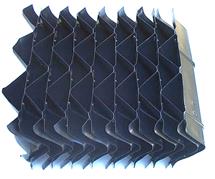
Example of a Cellular Style Drift (Mist) Eliminator
Water
distribution
Water distribution is the single most important
operating variable that ensures full performance of the stripper. Uneven water
distribution can have the following effects.
Loss of Performance – If all the surface area of the
packing is not wetted, then less surface area will be available for mass
transfer.
Plugging – If some areas of the packing are
intermittently wetted, scaling and solids deposition will occur. In areas not flushed with a sufficient flow
of water, thick biofilms may form.
Air bypass – The air will follow the path of least
resistance. The parts of the tower with
the greatest water flow will receive the least air flow and the part with the
least water will receive the most air. This contributes to the loss of
performance.
Even water distribution across the top of the
packing is absolutely essential to full performance and trouble free
operation. There are several good ways
to distribute water across the top of the packing depending on the
configuration of the tower. The choice is between single nozzle coverage with a
solid cone nozzle and multiple nozzles that provide overlapping patterns. A few guidelines are useful to help the
selection process.
1. Avoid
small holes. Small holes tend to plug up
and/or biofoul. The minimum orifice in any systems should be 12 mm.
2. Avoid
high pressure nozzles. High pressure
systems waste energy, create small droplets, require more maintenance and are generally
more expensive.
3. Avoid
moving parts. Moving parts such as
spinners, rotating arms and oscillating bars tend to have shorter useful lives
and require more maintenance than fixed systems.
4. Avoid
spraying water on the wall. The edge of
the spray should hit at the corner where the packing meets the wall. Water that hits the wall tends to stay on the
wall and does not travel through the packing.
For counter flow systems, the simplest and best
system is a pressurized nozzle arrangement.
Nozzles mounted in a piping system can provide even distribution, access
to the packing and unrestricted air flow through the tower. They are simple to build and support. Their only drawback is the pressure required
to operate the nozzle. Operating pressure
should be between 2 – 5 psi.
Small round counter flow towers up to 3-4 ft. in
diameter should use a single, solid cone, round pattern nozzle in the center of
the tower. It is more difficult to
achieve an even pattern of droplets with multiple nozzles in a round
tower.
Small square towers up to 3-4 ft. on a side should
use a single, solid cone, square pattern nozzle in the center of the
tower. However, it is easier to get even
coverage with multiple nozzles in a square or rectangular tower than in a round
tower.
The alternative to pressurized piping systems is a
pan distribution system. Pan
distribution systems operate with very low head requirements and space
requirements. There are two main
drawbacks to these systems. The weight
of the water in the pan must be considered when designing the structure. The other drawback is the obstruction of the
pan to the air flow in counter flow systems.
Provisions must be made for the air to flow around or through the
pan.
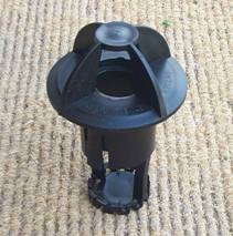
Pan distribution systems must use target nozzles to
achieve a sufficiently even water pattern.
Drip type pans with small holes cannot provide an even
distribution. The small holes in drip
pans are also very easily plugged. Here is an example of a target nozzle.
For cross flow systems, pan distribution systems are
best for all but the smallest system.
For very small systems, a header pipe with cover plate distribution
system is best. Pressure nozzles do not work well for cross flow systems.
Media
Selection
Although many different materials have been used for
packings in CO2 strippers, most modern strippers are designed with one of two
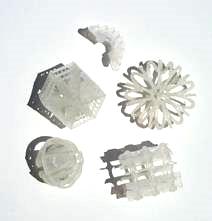
types of media. The older types of media are known as random or dumped packings
and come in a variety of shapes and sizes.
Here are a few examples.
The newer types of packings are known as structured
media and have been used in aquaculture for the past 30 years. They are also known as cellular or film fills
and are available in numerous shapes and configurations. Structured packings have a number of
advantages that make them the packing of choice for CO2 strippers. This is a
typical example of cross corrugated structured packings
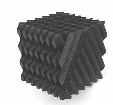
Structured
packings are typically constructed of vacuum formed sheets of PVC (polyvinyl
chloride). Continuous vacuum forming is a high speed automated process that can
efficiently produce large amounts of material.
This method of construction allows structured packings to be produced
for a much lower cost per unit surface area than injection molded, random
dumped packings. PVC is a relatively low cost resin with much better mechanical
properties than PP (polypropylene) or HDPE (high density polyethylene).
In
order for the media to maximize mass transfer, water must be able to wet the
surface and form a film. PVC is
initially hydrophobic but normally becomes fully wetable within 1 to 2 weeks.
Most random medias are made from HDPE or PP that take several months to become
fully wetable.
The
vacuum formed sheets of PVC are welded or glued together to form rectangular
blocks. Some packings have internal "tubes" that only allow flow
along one axis of the block. Other types of structured packings known as cross
corrugated packings allow flow along 2 axes of the block. Most structured
packings used in CO2 strippers are of the cross corrugated type.
An
important feature of structured medias is their very high void fractions. Void
fraction is the percentage of open space or volume in the packing. To phrase it
another way, void fraction is the space not occupied by the packing itself.
High void fractions allow free and unrestricted flow of water or air and
water. A modern packing like structured
packing for CO2 stripping applications should have a void fraction of 95% or
greater.
Structured
medias are resistance to plugging or clogging. This parameter is very important
but difficult to quantify. Plugging or clogging of a stripper can happen
through mechanical trapping of particles in the same way a screen or other
particulate filter works. Plugging can also result from the growth of the
biofilms and bridging across the spaces within the packing. Plugging tendency
for various packings can be predicted or compared by looking at the void
fraction and free passage diameter. The free passage diameter is the more
important variable. The best way to understand free passage diameter is to
imagine a marble or ball bearing being dropped through the packing. The size of
the largest ball that will pass through the packing is the free passage
diameter.
Another
feature of structured media is excellent mechanical strength. In a large
stripper, it is very desirable that the media be able to safely support the
weight of one or more workers. Aside from supporting maintenance traffic, good
mechanical strength means better dimensional stability, reduced vessel support
requirements and longer life. Unlike any other type of packing, structured
packings can span distances of up to 10 ft. between supports. It is more common
however to support them on beams that are 2 to 3 ft on center.
CO2
strippers come in all shapes and sizes and structured media can be cut to fit
any shape vessel. If maintenance is
required due to plugging or the need to sterilize the system between crops,
structured packings can be easily moved
with a minimum of labor and specialized equipment. The large blocks are easy to
handle and move around. Random packings
must be moved with shovels or buckets and are cumbersome to handle.
CO2
strippers are sometimes built with out any fans. These systems depend on diffusion, thermal
convection or water flow induced convection to carry away the CO2 laden air. These systems are typically much less
efficient than ones designed with fans to move air through the stripper. Here are a couple performance curves showing
the removal efficiency versus air flow for two temperature levels. The basis for the design is counter flow
operation, 30 ppm CO2 entering and 10 ppm leaving. The packing is a cross corrugated structured
media with a 19 mm sheet spacing. The system is set for isothermal conditions.
(i.e. no heat transfer between air and water)
These calculations do not take into account any removal or addition of
CO2 due to chemical equilibrium reactions.
Example #1

Example #2
The
flows are given in terms of air velocity and specific water loading. In this way the towers can be scaled to fit
any size application.
These curves illustrate the type of design information
necessary to minimize both capital costs and operating costs. By determining the point at which higher air
velocities do not produce further benefits, one can minimize the tower size and
minimize the heat loss from the exhaust air stream.
Common Mistakes
There
are a number of common mistakes made by people trying to build CO2 strippers.
1. Using waterfall type systems
Water cascading over a weir or pouring in a solid stream from a pipe does not
generate enough surface area to achieve much mass transfer. It is a waste of pump head energy to let
water fall in an unbroken stream into a pool.
2. Totally enclosed vessels with no air movement.
If
a CO2 stripper does not have any air movement through the vessel, no CO2 will
be removed from the water. There will be
a small amount of CO2 removed when the unit is first used but as the CO2 builds
up in the vessel, the CO2 transfer out of water slowly decreases as the CO2
concentration in the air increases. When the CO2 in the air reaches equilibrium
with the CO2 in the water no further removal of CO2 from the water is possible.
3. Uneven or inadequate water
distribution.
This
is one of the most common problems in packed towers of all kinds. Continuous and even distribution of water
over all of the packing surfaces is essential to reach full performance. If the packing surface is not wetted, it will
not do any work. A good water distribution
system is a small part of the cost of any tower but it is a major contributor
to overall system performance.
4. Using inefficient or unsuitable
packings.
Many
people try to reinvent the wheel by utilizing some common or cheap objects for
tower packings. The truth is that almost
anything will work as a tower packing.
Old car bodies will work if you use enough of them. The problem is that old car bodies are not
the most economical choice when you consider both the capital and operating
costs of the system. Ping pong balls,
lava rock, milk crates, window screens and other materials will also do the job
but again, they are not the most economical choice. Structured packings are used in a wide
variety of industries for heat and mass transfer applications. Up to this point in time, no one has
developed a better or more cost effective media for gas-liquid mass transfer
operations.
Conclusions
There
are many different ways to remove CO2 from the water in recirculating
aquaculture systems. From the standpoint
of minimizing capital, operating and maintenance costs, the best solution to
the problem is an induced draft, cross flow stripper with structured
packing. They are simple to build and
operate and have several auxiliary benefits including biofiltration and
reoxygenation of the water. If designed
properly, they can also be used for cooling purposes.
Acknowledgements:
The
calculations in this paper were performed with the use of VOC design software
developed by MRL Corporation. This software
is available for sale from:
MRL
Corporation
15590
Triple Crown Court
Ft.
Myers, FL 33912 USA
Tel# 239-481-9653
Fax# 239-481-2866
Contact:
Marcel LeFevre
Email:
mr_cooling_tower@compuserve.com
©2002
by L. S. Enterprises. All rights
reserved. No part of this publication may be reproduced or transmitted in any
form or by any means electronic or mechanical, including photocopy, recording,
or any information storage and retrieval system, without permission in writing
from the publisher.
Published by L. S.
Enterprises
PO Box 13925
Gainesville,
FL 32604 USA
Author: Matt Smith
Office 1-352-379-5626
Mobile
1-239-851-1175
Fax
1-866-706-1775
Email: mattsmith@biofilters.com
Rev. 8/07/2013